
- Sat Dec 21, 2019 12:17 am
#327
 Add description
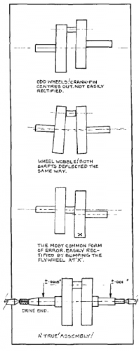
Truing the crank.PNG (24.08 KiB) Viewed 1710 times
 Add description
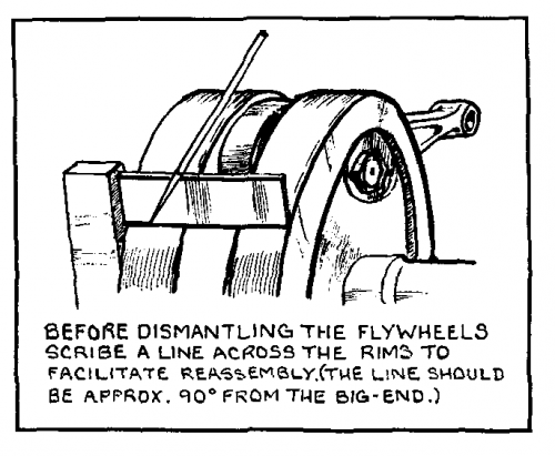
fly wheel disassembly.PNG (29.67 KiB) Viewed 1711 times
I'm sure you all recall my rotor explosion that snapped the left crank spindle on my '99 Bullet 500. Originally, I planned to tear down the engine, remove the crank, separate the flywheels then remove the broken crank spindle and replace it with one from across the pond. While I was waiting for the crank spindle, I instead tried to drill and tap the broken spindle, which has thus far worked well for about 4000 miles now.
However, I am concerned that at some point, I will have to bite the Bullet and remove the crankshaft . This has caused me sleepless nights thinking about what I could foul-up by taking the engine apart. So, in preparation, I have been looking for a good description of the correct procedure. I stumbled upon a PDF of an out of print book from 1986 printing that describes vintage motorcycle restoration process. It describes several procedures that would minimize foul-up situations. My first concern is making certain the rebuilt crank, fly-wheel, and spindles and on the same axis. I can envision making a mistake and have the crank out of whack and start vibrating like a Bronco. You can see from the diagrams the problems that could occur. One way to stave off failure is by scribing a line mark across both flywheels to have a reference mark for reassembly. This reference mark would not guarantee the proper alignment upon reassembly, but would give a good start.
However, I am concerned that at some point, I will have to bite the Bullet and remove the crankshaft . This has caused me sleepless nights thinking about what I could foul-up by taking the engine apart. So, in preparation, I have been looking for a good description of the correct procedure. I stumbled upon a PDF of an out of print book from 1986 printing that describes vintage motorcycle restoration process. It describes several procedures that would minimize foul-up situations. My first concern is making certain the rebuilt crank, fly-wheel, and spindles and on the same axis. I can envision making a mistake and have the crank out of whack and start vibrating like a Bronco. You can see from the diagrams the problems that could occur. One way to stave off failure is by scribing a line mark across both flywheels to have a reference mark for reassembly. This reference mark would not guarantee the proper alignment upon reassembly, but would give a good start.
Attachments
Truing the crank.PNG (24.08 KiB) Viewed 1710 times
fly wheel disassembly.PNG (29.67 KiB) Viewed 1711 times
