
- Sun Mar 29, 2020 6:54 pm
#839
 Add description
IMG_5002.JPG (1.84 MiB) Viewed 2035 times
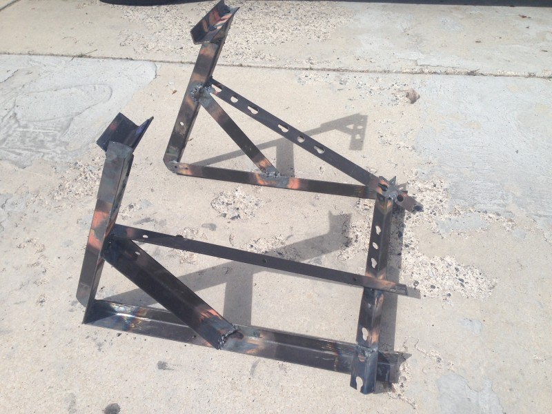 Home made Paddock stand from old bed frame.
IMG_5010.JPG (2.88 MiB) Viewed 2035 times
I don't know about you, but after about a year of riding and parking a bullet, the centre stand gets a bit wobbly and starts to lean to one side. Later the centre stand no longer keeps the rear wheel off the ground. After consulting folks on this board and the Classic board, it is clear that the problem is that over time the steel rear engine plates get fatigued and the spindle for the centre stand causes the hole in the steel plates to "oval" which in turn causes the centre stand to get wobbly. I don't know if this is a problem for the UCE or Interceptor bikes, but it is a common problem for the Bullet Models.
I tried to find a source for new steel Lower rear engine plates, Hitchcock's had the plate for the right side, but none remained for the left. So, I ordered a new right side engine plated. It is unclear what the difference between the Indian/UK engine plates and the USA version of the engine plates, but apparently there is some difference. When my right side plate cam in, I realized that I would have to get the rear wheel off the ground while I removed the center stand bolts. I looked online and found several China paddock stand for sale from $50-$150 or more. But then, I had a great "idea" to practice my welding by making a "paddock" stand to lift the rear wheel off the ground. I had an old bed frame in the basement that had been there for at least 20 years and I decided it was time to put it to work. I took the angle iron from the bed frame and cut it to the lengths which seemed about right and started the build. I found out quickly that my welding skills were not up to the 8th grade shop class, but, I kept at it as can be seen in the photo below:
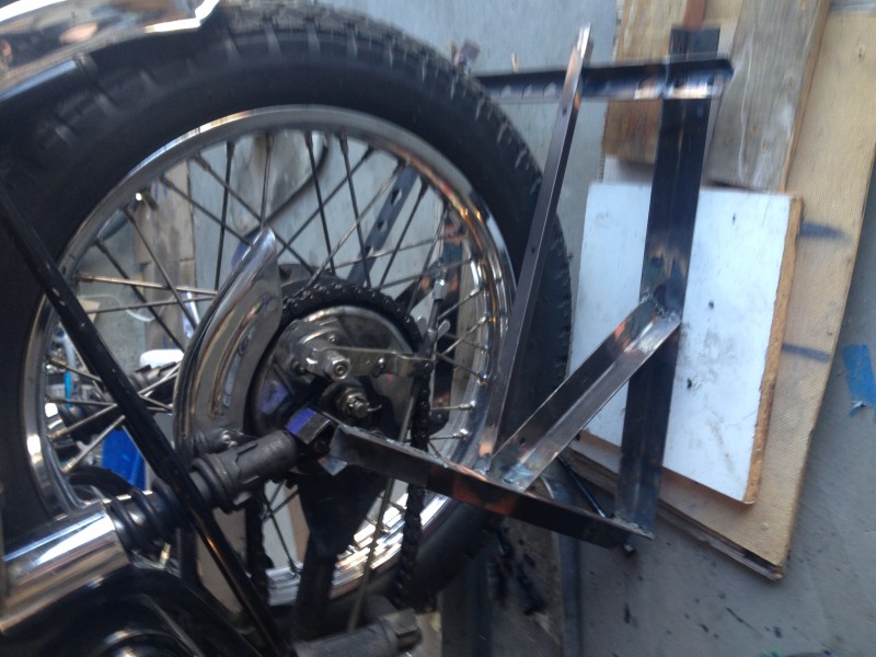
As you might expect, the paddock stand was about 2 inches shorter than it needed to be.....oh well. I pushed on by placing boards under the stand.
I tried to find a source for new steel Lower rear engine plates, Hitchcock's had the plate for the right side, but none remained for the left. So, I ordered a new right side engine plated. It is unclear what the difference between the Indian/UK engine plates and the USA version of the engine plates, but apparently there is some difference. When my right side plate cam in, I realized that I would have to get the rear wheel off the ground while I removed the center stand bolts. I looked online and found several China paddock stand for sale from $50-$150 or more. But then, I had a great "idea" to practice my welding by making a "paddock" stand to lift the rear wheel off the ground. I had an old bed frame in the basement that had been there for at least 20 years and I decided it was time to put it to work. I took the angle iron from the bed frame and cut it to the lengths which seemed about right and started the build. I found out quickly that my welding skills were not up to the 8th grade shop class, but, I kept at it as can be seen in the photo below:
As you might expect, the paddock stand was about 2 inches shorter than it needed to be.....oh well. I pushed on by placing boards under the stand.
Attachments
IMG_5002.JPG (1.84 MiB) Viewed 2035 times
IMG_5010.JPG (2.88 MiB) Viewed 2035 times

